Description
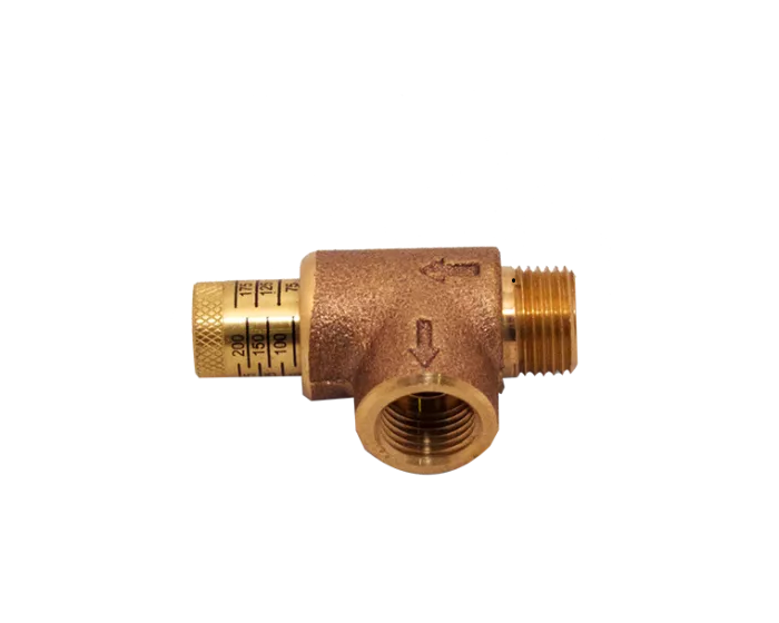
Designed for use in grid systems or any sprinkler system where pressure relief is required. The Adjustable Pressure Relief Valve can be adjusted from 75-175 psi. Adjustment to the desired pressure is achieved with the use of an approved fire sprinkler system pressure gauge. The adjustment cap is “diamond” knurled for easy adjustment. The body is cast bronze* and marked with directional arrows for proper flow indication. The pressure markings on the adjustment cap are for reference only. Use the system gauge for proper relief setting.
Installation
Installation of the Adjustable Pressure Relief Valve is accomplished with tools readily available on the job site utilizing approved installation methods. Do not install outlet piping until relief pressure has been set. To set relief pressure, rotate adjustment cap clockwise until seated. Pressurize sprinkler system to the pressure that you wish to provide relief. Once system pressure has been set slowly turn pressure relief valve adjustment cap counter clockwise until the valve outlet starts to “spit” water from the system (bleed off pressure). Once the valve starts to “spit” then slowly close the valve cap until the valve stops “bleeding off” pressure. Check the system pressure gauge to make sure pressure is maintained at the relief pressure. Repeat steps until proper relief pressure has been set. Make sure to test setting by pressurizing system above relief setting to verify proper relief valve function. Use an appropriate thread sealant such as PipeFit or PipeFit AS to prevent leakage of the threaded connections. Refer to Authority Having Jurisdiction or NFPA13 for proper installation location in the sprinkler system.
| Material Specifications | Brass |
|---|---|
| PSI | 175 |
| Capacity (Gal) | 1/2" |
| Shipping Height | 1 |


